Related Articles
-
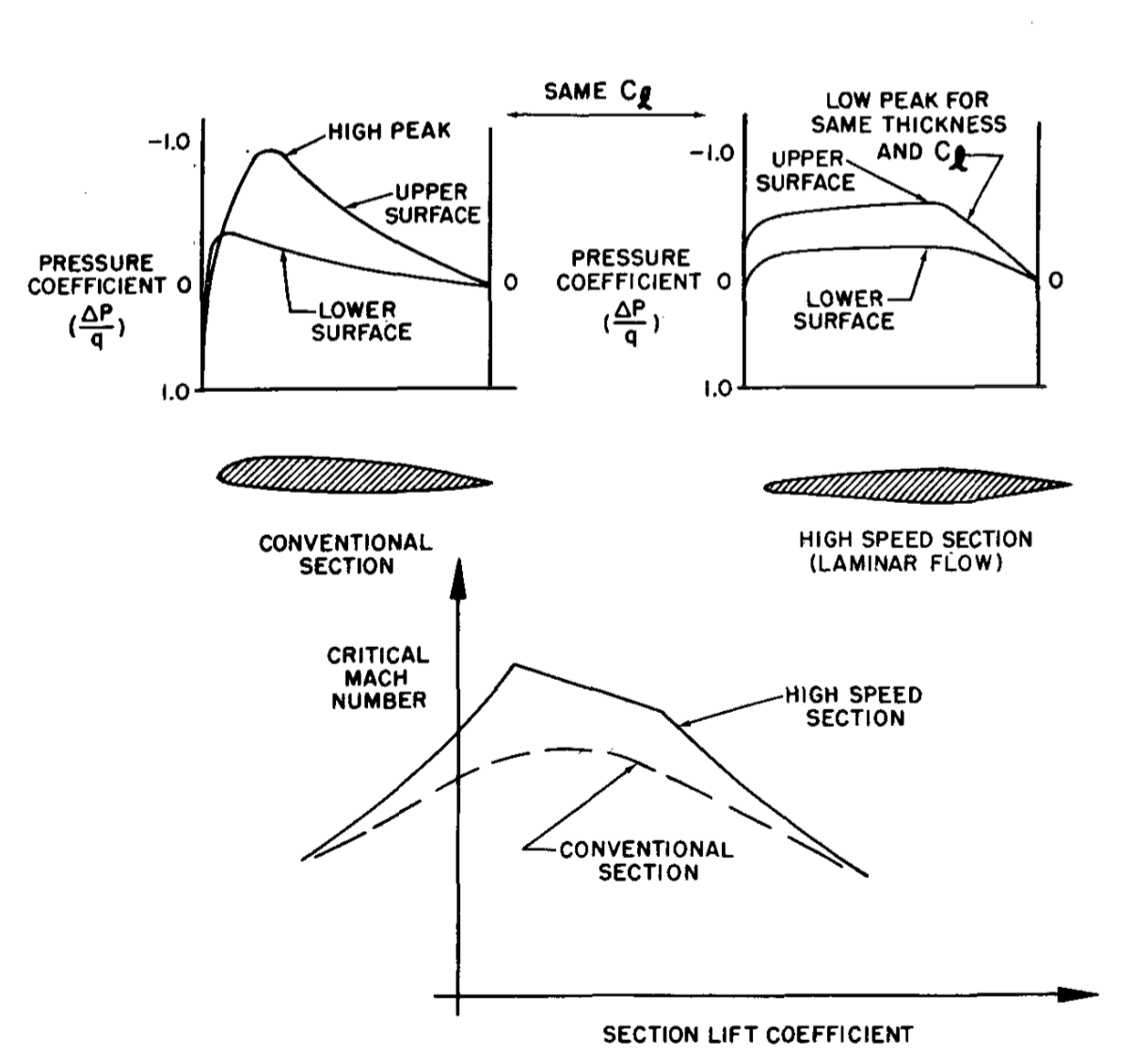
Critical Mach and Airfoil Design
You are unauthorized to view this page. Please login your credentials Username Password Remember Me Forgot Password
-
Boundary Layer Control Devices
You are unauthorized to view this page. Please login your credentials
-
-
-
-
-
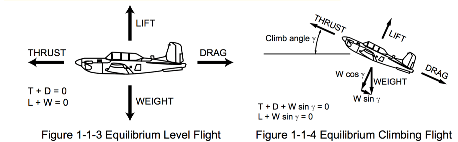
Topic of the day: Aerodynamics/Equilibrium
You are unauthorized to view this page. Please login your credentials
-
