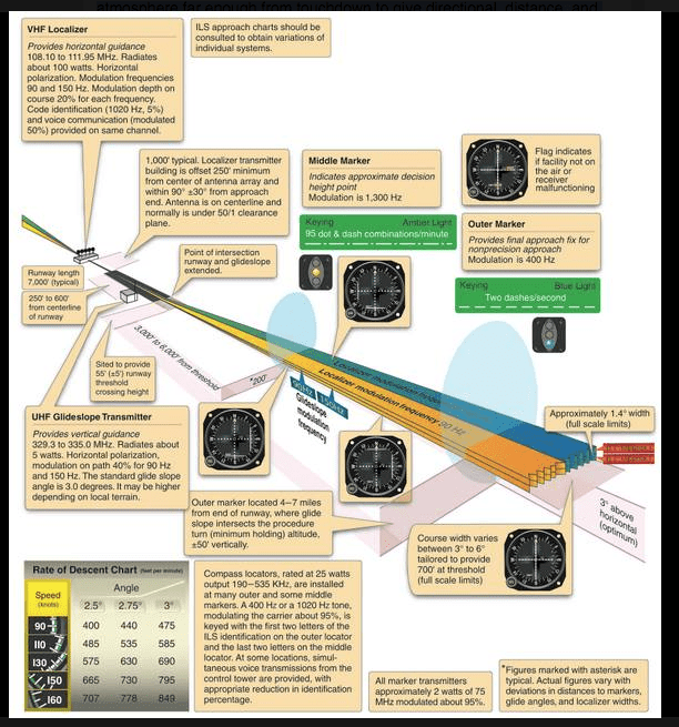
ILS System
admin@readysettakeoff.com
Related Articles
-
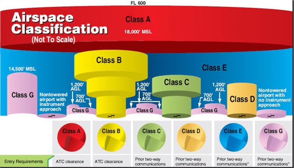
Airspace Review
Jet Brain, , Navigation, 0
You are unauthorized to view this page. Please login your credentials Username Password Remember Me Forgot Password
-
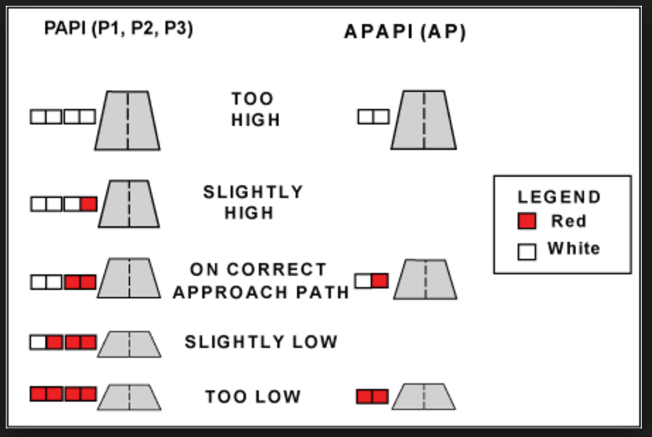
PAPI Systems
Jet Brain, , Navigation, 0
You are unauthorized to view this page. Please login your credentials
-
Descending below the DH on approach
Jet Brain, , Navigation, 0
You are unauthorized to view this page. Please login your credentials
-
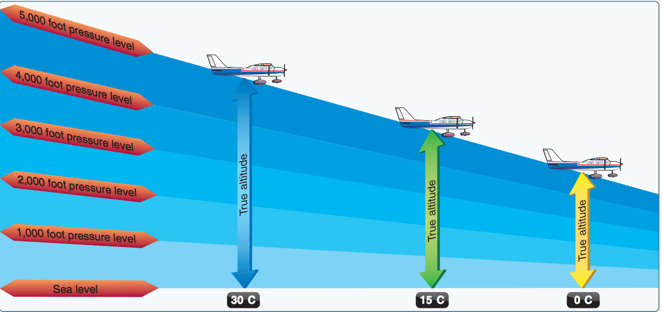
Effects of Temperature on Altitude
Jet Brain, , Navigation, 0
You are unauthorized to view this page. Please login your credentials
-
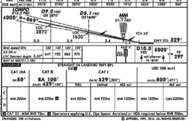
Approach Minimums
Jet Brain, , Navigation, 0
You are unauthorized to view this page. Please login your credentials