Turning flight is described as changing the direction of the airplane’s flight path by reorienting the lift vector in the desired direction. During a turn, the lift vector is divided into two components, a horizontal component (LH) and a vertical component (LV). The horizontal component of lift, called centripetal force, accelerates the airplane toward the inside of the turn. In straight and level flight (constant altitude, constant direction) total lift is equal to weight, but in a turn, only the vertical component of the lift vector opposes weight. If the pilot does not increase the total lift vector, the airplane will lose altitude because weight will be greater than LV. The increased lift is normally obtained by increasing the angle of attack, i.e. pulling back on the stick. As the stick moves aft, G- forces build up. Screen Shot 2016-07-06 at 10.58.01 AM
Increasing the lift produced by the wings increases the load on the airplane. Load factor (n) is the ratio of total lift to the airplane’s weight. It is sometimes called Gs since it is the number of times the earth’s gravitational pull felt by the pilot. For example, a 3,000 pound airplane in a 60o angle of bank turn must produce 3,000 pounds of vertical lift to maintain altitude. There- fore, the wings must produce 6,000 pounds of total lift so the airplane experiences a load on its wings that is twice the force due to gravity, or 2 Gs. One “G” is what we experience just sitting or walking.
n= L/W or L=W•n
In maneuvering flight, the amount of lift produced by an airplane is equal to its weight (W) multiplied by its load factor (n). By substituting W · n into the lift equation and solving for V, we can derive an equation for stall speed during maneuvering flight. This is called accelerated stall speed because it represents the stall speed at velocities greater than minimum straight and level stall speed, and load factors greater than one. Phi (φ) is the angle of bank associated with the load factor (n).
Maneuvering the airplane will significantly affect stall speed. Stall speed increases when we induce a load factor greater than one on the airplane. The figure provided is a generic chart that can be used for any fixed wing aircraft and assumes a constant altitude turn. It lists the load factors and percent increase in stall speed for varying angles of bank. Notice that above 45 degree angle of bank the increase in load factor and stall speed is rapid. This emphasizes the need to avoid steep turns at low airspeeds. An airplane in a 60 degree angle of bank experiences 2 Gs, but has an accelerated stall speed that is 40% greater than wings level stall speed.
A quick method for calculating accelerated stall speed is to round your normal stall speed off to a higher, round number and multiply it by the square root of the number of Gs sustained. For exScreen Shot 2016-07-06 at 10.58.07 AMample, if stall speed is 92 kts and a 2 G maneuver is performed, accelerated stall speed can be estimated by rounding 92 kts up to 100 kts, then multiplying by the square root of two (1.4).
DEFINITIONS 
A load is a stress-producing force that is imposed upon an airplane or component. Strength is a measure of a material’s resistance to load. There are two types of strength: Static strength and fatigue strength. Static strength is a measure of a material’s resistance to a single application of a steadily increasing load or force. Static failure is the breaking or serious permanent deformation of a material due to a single application of a steadily increasing load or force. For instance, a pencil breaks when too much force is applied and its static strength is exceeded.
Fatigue strength is a measure of a material’s ability to withstand a cyclic application of load or force, i.e., numerous small applications of a small force over a long period of time. Fatigue failure is the breaking (or serious permanent deformation) of a material due to a cyclic application of load or force. Breaking a wire coat hanger by bending it back and forth demonstrates fatigue failure. Airplanes may experience fatigue failure on many components (landing gear struts, mounting brackets) due to the numerous arrested landings, catapult shots, and high G maneuvers performed in normal operation. The components are designed to withstand repeated loads, but not forever. Service life is the number of applications of load or force that a component can withstand before it has the probability of failing. Fatigue strength plays a major role in determining service life. Service life may apply to an individual component, or to the entire airframe.
When a metal is subjected to high stress and temperature it tends to stretch or elongate. This is called plastic deformation or creep. Engine turbine blades are periodically monitored for creep damage due to high heat and stress. Modern supersonic aircraft may suffer from creep damage on the skin of the airplane, especially on the leading edge of the wings.
The structural limits of an airplane are primarily due to the metal skeleton or airframe. Any time a wing produces lift, it bends upward. The wing may permanently deform if lift becomes too great. Airframe components, particularly the wings, determine the maximum load that the airplane can withstand. The two greatest loads on an airplane are lift and weight. Since weight doesn’t vary greatly from one moment to the next, lift will be the force that causes the maximum load to be exceeded.
It is difficult to measure the amount of lift produced by the airplane, but it is relatively easy to measure acceleration. Since acceleration is proportional to force (Newton’s Second Law), if we know the weight of the airplane, we can determine the amount of lift by monitoring the airplane’s acceleration. Since load factor is a ratio of an airplane’s lift to its weight, and the mass being accelerated by lift and weight is the same mass, load factor is actually the acceleration due to lift expressed as a multiple of the earth’s acceleration, and can easily be measured by an accelerometer.
Structural considerations determined by the airplane’s mission and desired service life force a manufacturer to meet certain limits, such as maximum load factor, airspeed and maneuvering limitations. These design limits include the limit load factor, ultimate load factor, redline airspeed and maneuvering parameters.
Limit load factor is the greatest load factor an airplane can sustain without any risk of permanent deformation. It is the maximum load factor anticipated in normal daily operations. If the limit load factor is exceeded, some structural damage or permanent deformation may occur. Aircraft will have both positive and negative limit load factors.
 
Overstress/Over-G is the condition of possible permanent deformation or damage that results from exceeding the limit load factor. This type of damage will reduce the service life of the airplane because it weakens the airplane’s basic structure. Overstress/over-g may occur with- out visibly damaging the airframe. Inside the airplane are a variety of components, such as hydraulic actuators and engine mounts, which are not designed to withstand the same loads that the airframe can. Before the airframe experiences static failure these components may break if overstressed. The wing will not depart the airplane if the limit load factor is exceeded, but if an engine mount breaks, a fire could result from fuel spewing on hot engine casing. Any time an airplane experiences an overstress, maintenance personnel must inspect to determine whether damage or permanent deformation actually occurred. Always report an overstress/ over-G to maintenance. Whether or not deformation or damage occurs depends on the elastic limit of the individual components.
If a rigid metal object, such as a wing, is subjected to a steadily increasing load, it will bend or twist. When the load is removed, the component may return to its original shape. The elastic limit is the maximum load that may be applied to a component without permanent deformation. When a component is stressed beyond the elastic limit, it will experience some permanent deformation, but may still be usable. If the force continues to increase, the component will break. To ensure the airplane may operate at its limit load factor without permanent deforma- tion, the limit load factor is designed to be less than the elastic limit of individual components. This virtually guarantees the airplane will reach its expected service life.
Ultimate load factor is the maximum load factor that the airplane can withstand without structural failure. There will be some permanent deformation at the ultimate load factor, but no actual failure of the major load-carrying components should occur. If you exceed the ultimate load factor, structural failure is imminent (something major on the airplane will break). The ultimate load factor should be avoided since the typical airplane is rather difficult to fly after its wings tear off. The ultimate load factor is 150% of the limit load factor.
V-N / V-G DIAGRAM 
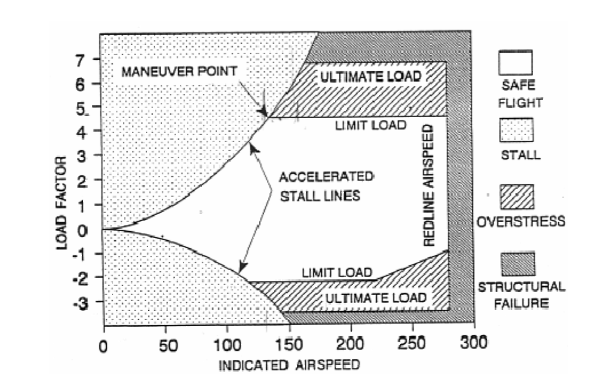
Screen Shot 2016-07-06 at 10.58.16 AMThe V-n diagram or V-G diagram is a graph that summarizes an airplane’s structural and aerodynamic limitation. The horizontal axis is indicated airspeed, since this is what we see in the cockpit. The vertical axis of the graph is load factor, or Gs. The V-n diagram represents the maneuvering envelope of the airplane for a particular weight, altitude, and configuration.
Accelerated stall lines, or lines of maximum lift, represent the maximum load factor that an airplane can produce based on airspeed. The accelerated stall lines are determined by CLmax AOA. They are the curving lines on the left side of the V-n diagram . If one tries to maintain a constant airspeed and increase lift beyond the accelerated stall lines, the airplane will stall because we have exceeded the stalling angle of attack. As airspeed in- creases, more lift can be produced without exceeding the stalling angle of attack.
The limit load factors and ultimate load factors, both positive and negative, are plotted on the diagram. These lines represent the manufacturer’s and the military’s structural limitations.
Any G load above the limit load factor will overstress the airplane. Any G load above the ulti- mate load factor is very likely to cause structural failure. Notice that the positive and negative limit load factors are different. Since the pilot cannot sustain a negative acceleration much greater than three Gs, the designer can save some structural weight by reducing the airplane’s ability to sustain negative Gs. For this reason, most maneuvers are performed with positive accelerations.
The point where the accelerated stall line and the limit load factor line intersect is called the maneuver point. The IAS at the maneuver point is called the maneuver speed (Va) or cornering velocity. It is the lowest airspeed at which the limit load factor can be reached. Below the maneuver speed, we can never exceed the limit load factor because the airplane will stall before the limit load factor is reached. The vertical line on the right side is called the redline airspeed, or VNE (Velocity never-to- exceed). Redline airspeed is the highest airspeed that an airplane is allowed to fly. Flight at speeds above VNE can cause structural damage. VNE is determined by one of several methods: MCRIT, airframe temperature, excessive structural loads, or controllability limits.
If an airplane reaches its critical Mach number (MCRIT), and is not designed to withstand super- sonic airflow, the shock waves generated may damage the structure of the airplane. Redline airspeed for these aircraft will be slightly below the airspeed at which they will achieve MCRIT.
Redline airspeed may also be used to set limits on airframe temperature. As airspeed increases, the airplane encounters more air particles producing friction which heats up the airframe. This heating can be extreme and hazardous at high speeds. Once the temperature becomes excessive, the airframe may suffer creep damage.
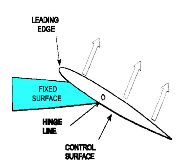
Excessive structural loads may be encountered on components other than the main structural members. Control surfaces, flaps, stabilizers, and other external components are often not able to withstand the same forces that the wings or fuselage can withstand. Deflecting control surfaces at very high airspeeds may create sufficient forces to twist or break the wing or stabilizer on which they are located.
Controllability may determine the redline airspeed on aircraft with conventional control systems. At high airspeeds, dynamic pressure may create forces on the control surfaces which exceed the pilot’s ability to overcome. Or, due to the aeroelasticity of the controls surfaces, full deflection of the cockpit controls may cause only small deflection of the control surfaces. In either case, the pilot will be unable to provide sufficient control input to safely maneuver the airplane.


©2024 Ready Set Takeoff

Log in with your credentials

Forgot your details?