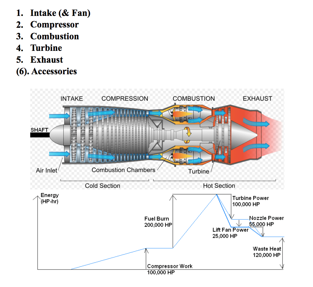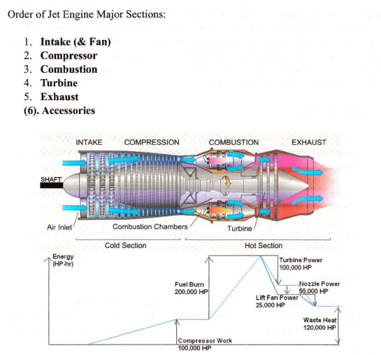
Operation- Airflow from the intake fIrst enters the compressor. Typically, the compressor
consists of centrifugal-flow and/or axial-flow compresso,rs, or multiples of each. Intake
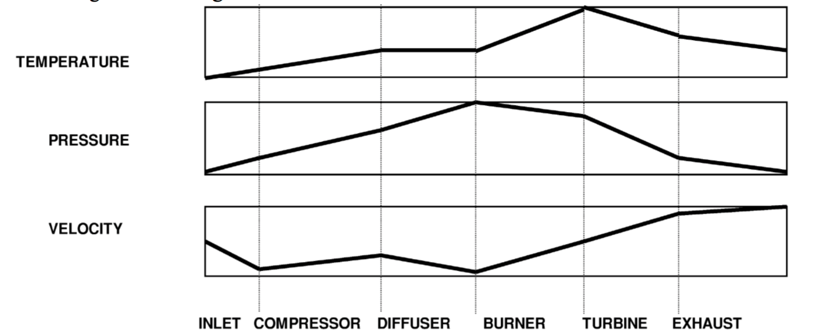
air is sped up with a rotor blade, then slowed slightly with diffuser/stator vane. Air
velocity increases with each rotor blade (high kinetic energy). High velocity air enters
diffuser/stator vane, reducing velocity.
The reduction in air velocity results in an increase
in air pressure, converting velocity energy into pressure energy. Depending on design,
this sequence repeats through multiple compressor stages. Many gas turbine engines use
multiple compressors in tandem on separate shafts, turning at differing speeds. The
highest total air velocity in the compressor section is at the inlet of the last diffuser. The
lowest air velocity in the entire engine is at the diffuser outlet & combustor inlet.
The highest static air pressure in the entire engine is at the outlet of the last diffuser &
combustor inlet. The sum of all compressor components which share a common shaft are
considered one compressor. In the combustion section, fuel nozzles atomize fuel in the
high velocitylhigh pressure air leaving the compressor section. Atomized fuel is ignited
during start by igniters, and sustained with a fIreball in the burner can. Combustion
greatly increases the volume of gases available. Combusted expanding gases are ported
through the high-pressure turbine nozzle to the turbine section.
The highest total air velocity is found at the turbine nozzle prior to the turbine section. A portion of the expanding gas kinetic energy is extracted by the turbine section and converted to shaft
horsepower used to drive the compressor section & accessory section. Approximately
60% of expanded combustion gas is extracted by the turbine to drive the compressor and
accessory sections. Approximately 40% of expanded combustion gas is available to
directly develop useful thrust. Hot gases exiting the turbine section are ducted through
the exhaust section back into the atmosphere.
l. Intake (& Fan):
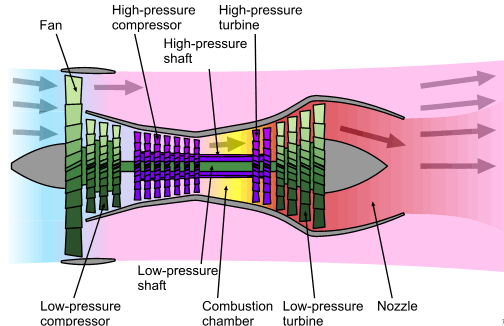
Turbofan- turbojet w/ shrouded fan prior to compressor. Fan driven by lowpressure
compressor shaft. Intake air divided into bypass air or inlet air to gas
turbine. Large volume of bypass air provides moderate acceleration, good
takeoff performance, low-altitude/speed efficiency, & quieter operation.
Turbojet core provides large acceleration & high cruise speed, with relatively
small volume of air.
Bypass air- ratio of air flowing through fan to amount of air flowing through
gas turbine. Higher bypass ratios yield greater fuel efficiency at low altitude.
2. Compressor:
Low-pressure compressor- forward most compressor. Driven by rearmost
low-pressure turbine. Rotational speed of low-pressure compressor shaft, read
in % design RPM, known as Nl. Nl shaft turns freely inside ofN2 shaft. Nl
is primary means of setting power on “speed rated” engine.
High-pressure compressor- second or intermediate compressor. Driven by the
high-pressure turbine. Rotational speed of high-pressure compressor shaft,
read in % design RPM, known as N2. N2 shaft counter-rotates concentrically
around the Nl shaft. Triple spool engines have an additional high-pressure
compressor (N3).
Spool- combination of compressor, shaft, & turbine.
Centrifugal-flow compressor- forces air outward, into diffuser. Diffuser slows
velocity, & increases air pressure.
Axial-flow compressor- forces air along longitudinal axis, into stator vanes.
Stator vanes reduce rotational flow, slow velocity, & increase air pressure.
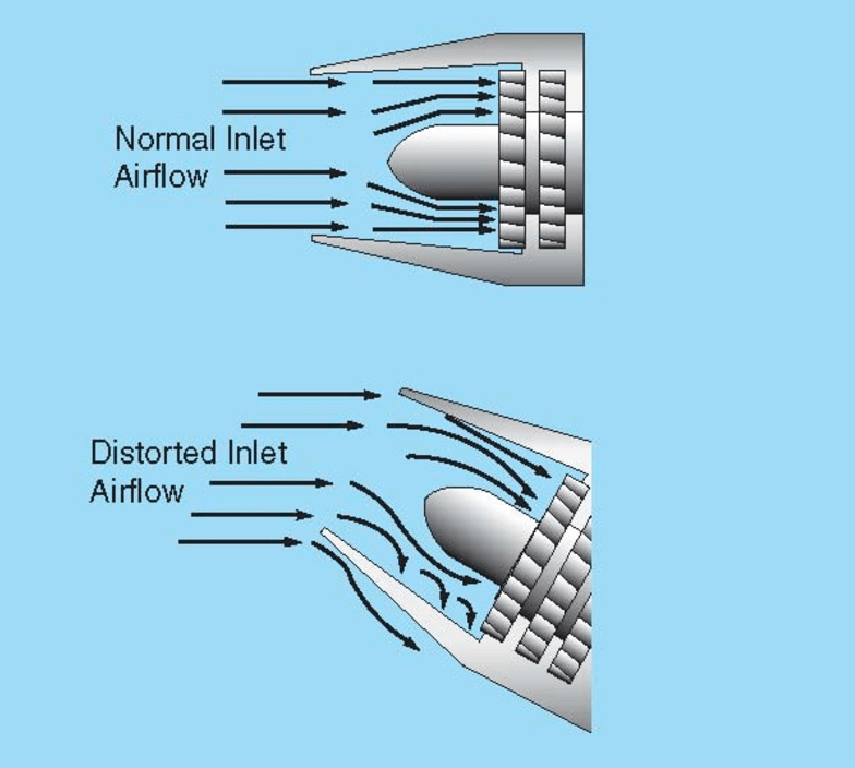
Compressor stall- distorted inlet air exceeds the fixed pitch compressor
blade’s critical angle of attack. Airflow to compressor slows or stagnates,
resulting in flow reversal. Indicated with loud “bang.” Reduce power setting,
reduce angle of attack, & increase airspeed to correct.
Bleed Air- air tapped from compressor section to used for pressurization,
heating, air-conditioning, thermal anti-ice, and other systems.
3. Combustion:
Burner Can (combustion chamber)- outer casing, with inner liner, which
contains fuel injection, ignition, & self-sustaining “fIreball.” Combustion
chamber ports expanding combustion gases via high-pressure turbine nozzle
into high-pressure turbine rotor.
4. Turbine:
Combustion chamber ports expanding combustion gases via high-pressure turbine
nozzle into high-pressure turbine rotor, then into low-pressure turbine rotor.
High-pressure turbine- extracts sufficient energy from expanding combustion
gases to drive high-pressure compressor (& accessory section). High-pressure
spool % design RPM indicated with N2.
Low-pressure turbine- extracts sufficient energy from combustion gases to drive
low-pressure compressor & fan. Low-pressure spool % design RPM indicated
with Nl.
TIT- Turbine Inlet Temperature. Highest temperature in a turbine engine.
ITT- Inter-stage Turbine Temperature. Measured between compressor & power
turbines.
TOT- Turbine Outlet Temperature.
TGT- Turbine Gas Temperature.
Flameout- fuel/air mixture is not sufficient to sustain combustion.
5. Exhaust:
Accelerated exhaust gasses provide thrust. Turbojet exhaust- hot exhaust gases
rip into cool atmosphere, resulting in loud wind shear. Turbofan exhaust- tapered
cone & struts mix hot primary exhaust with cool bypass airflow to produce total
thrust. Cool bypass air mixing with hot exhaust air, insulates/disperses hot
exhaust gasses & muffles loud wind shear.
EPR- Engine Pressure Ratio “eeper.” Ratio of turbine discharge (exhaust) to
engine inlet pressure (intake). EPR used to measure thrust produced, especially
for takeoff, of “pressure-rated” engine.
EGT- Exhaust Gas Temperature. Usually, main engine temperature gauge used to
prevent heat damage to turbine blades or other systems.
6. Accessory: (may not be considered major section in some applications)
Gear assembly, driven by high-pressure rotor shaft, which functions to drive
various accessories (oil pump, fuel pump, hydraulic pump, fuel control unit,
starter -generator).
Type to enter text


©2024 Ready Set Takeoff

Log in with your credentials

Forgot your details?